Inches & feet
Layer depths and joint widths are shown in inches. Site areas use square feet. Example dimensions are approximate conversions, not automatically rounded construction specifications.

FOR HOMEOWNERS, DESIGNERS & ENGINEERS
A complete guide to the material, the supporting assembly, and the decisions that create lasting performance.
U.S. MEASUREMENTS, PLAIN LANGUAGE
Layer depths and joint widths are shown in inches. Site areas use square feet. Example dimensions are approximate conversions, not automatically rounded construction specifications.
Water volume is shown in U.S. gallons. The published surface rate converts to about 933 gallons per square foot per hour, or 15.5 gallons per square foot per minute.
The published composite flexural strength converts to about 896 psi. This is a material bending-strength result, not a driveway’s allowable vehicle load.
PUBLISHED MATERIAL DATA
| Property | Published value / description | Specification context |
|---|---|---|
| Surface permeability | Approximately 933 U.S. gal / sq ft / hour | Published resin-bound surface figure. Installed system capacity is limited by base, soil, storage, and outlets. |
| Composite flexural strength | Approximately 896 psi | Material result; does not replace pavement structural design or establish axle-load capacity. |
| Selected UVR binder elongation | Up to 249% | Formulation-dependent binder property. Not 249% strain capacity for an installed stone pavement. |
| Freeze–thaw response | No measurable strength loss reported in University of Ottawa composite testing | Confirm the applicable test report, mix, cycles, and conditions for the selected system. |
| Surface composition | Natural aggregate + clear two-part polyurethane binder | Controlled mixing and installation form a connected porous finish. |
| UV performance | UV-stable resin-bound system available | Specify the correct binder and confirm compatibility with the aggregate. |
| Surface / base thickness | Project-specific | Determined by selected aggregate, loading, soil, and assembly. No universal thickness is presented. |
| Warranty / service life | Written project terms required | Coverage varies by installer and system. Request the actual Elevation project warranty before contracting. |
Published technology data describes tested materials and selected formulations, not a site-specific performance guarantee. Request supporting test documentation for the actual mix. Use the approved test report and complete project design for specification decisions.
THE ELEVATION SYSTEM ATLAS
Explore the typical assembly, support-grid section, three light-duty parking configurations, and both critical edge details. Overlay and drainage-strip studies show additional ways to resolve water.
Published example dimensions are converted to inches and shown approximately. These educational redrawings explain the assembly; they are not stamped construction drawings or a claim of compliance with a U.S. code or aggregate standard. Confirm the current approved mix and project design.
SECTION 01
An open-graded base supports the natural stone surface while preserving a pathway for water.
Published typical detail: wearing course approximately 1.50–1.97 inches; clear-stone base approximately 5.91–11.81 inches. Base aggregate is approximately 3/4 inch. Geogrid and prepared subgrade complete the detail.
SECTION 02
A layered assembly places a support grid beneath the wearing course, with water passing through the surface and base.
Published illustrated assembly: 1.5-inch wearing course, 1.5-inch support grid, and 10-inch clean-stone base over a specialized separation fabric. Soil infiltration must be assessed; clay does not automatically accept the water.
SECTION 03
Rigid curbs restrain the paving and protect the edge. A perforated underdrain can route stored water when specified.
Section A: surface approximately 1.50–1.77 inches; upper clear-stone layer 5.91–9.84 inches; lower clear-stone layer 1.97–3.94 inches. Structural internal geogrid and base/side reinforcement are shown in the source assembly.
SECTION 04
The stone system meets landscaping without the same rigid curb configuration. Side separation details keep soil from migrating into the base.
Section B: the same surface and stone-layer ranges as Section A, plus side geotextile and a minimum illustrated lateral extension of approximately 5.91 inches. The source edge angles are 35° and 45°; these are detail-specific, not universal driveway slopes.
SECTION 05
A lined transition protects the adjoining conventional pavement while the reservoir and underdrain manage collected water.
Section C: surface approximately 1.50–1.77 inches with a 1–5% illustrated surface slope, equivalent to approximately 1/8–5/8 inch of fall per foot. This source range is not a universal accessible-route specification.
SECTION 06
An edge is a small detail with a large job: restrain the surface, accommodate the interface, and preserve the intended base connection.
The source curb detail identifies a joint filler, the surface’s internal geogrid, the upper clear-stone base, and the lower reinforcement. Joint filler and curb geometry must be selected for the actual assembly.
SECTION 07
Resolve the connection between a porous surface and a conventional pavement before installation.
The source transition detail includes a 1/2-inch joint, joint filler, internal surface reinforcement, and an impermeable liner protecting the adjoining pavement structure. It is a transition detail, not permission to infiltrate against a foundation.
SECTION 08
The stone layer can be porous while the slab beneath it remains impermeable. The supporting surface determines where that water travels next.
An overlay thickness must come from its approved application specification. Maintain existing drainage, compatible repairs, movement joints, and threshold clearances. A porous overlay alone does not create infiltration through a concrete slab.
SECTION 09
A narrow stone strip receives nearby runoff and directs it into a receiving reservoir or underdrain.
Additional Elevation design study: width, stone depth, pipe diameter, and outlet are sized to the contributing area and soil conditions. Keep sediment out, protect foundations, and include a maintained overflow route.
Geotechnical review, soil infiltration testing, groundwater, expansive soil, foundations, utilities, run-on sediment, design storm, overflow route.
Pedestrian or vehicle duty, axle loads, turning areas, slopes, thresholds, edge restraint, drain transitions, movement details, accessible routes.
Aggregate grading, approved binder, mix ratio, surface thickness, base depth, dry substrate, temperature and moisture limits, cure and opening times.
A SIMPLE PLANNING EXAMPLE
Estimate water falling on an area before a designer sizes storage or outlets.
Uniform rainfall and constant assumed drainage are used only to explain the math. Drainage is limited to available water; no post-storm recession, maximum storage, clogging, soil change, run-on, or overflow is modeled. Enter a drainage assumption, not the published surface permeability. This is an educational graph, not a site hydrology model.
Volume = area × rainfall depth × 0.6234 US gallons. This is precipitation volume only. It excludes run-on, losses, discharge, and required safety factors; it is not a drainage design.
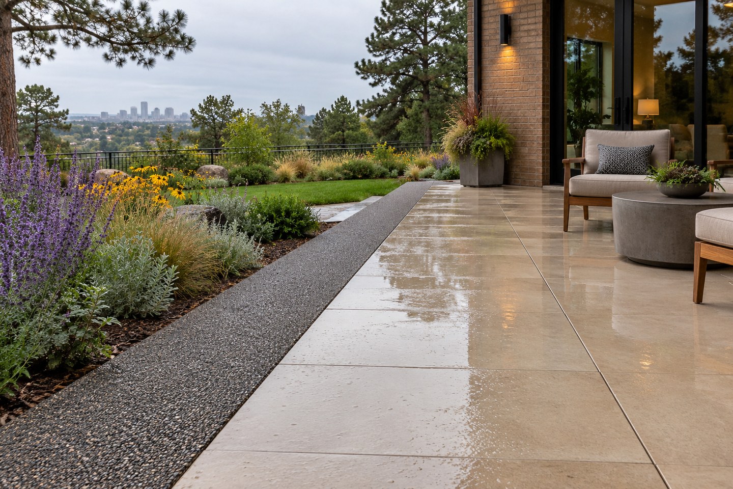
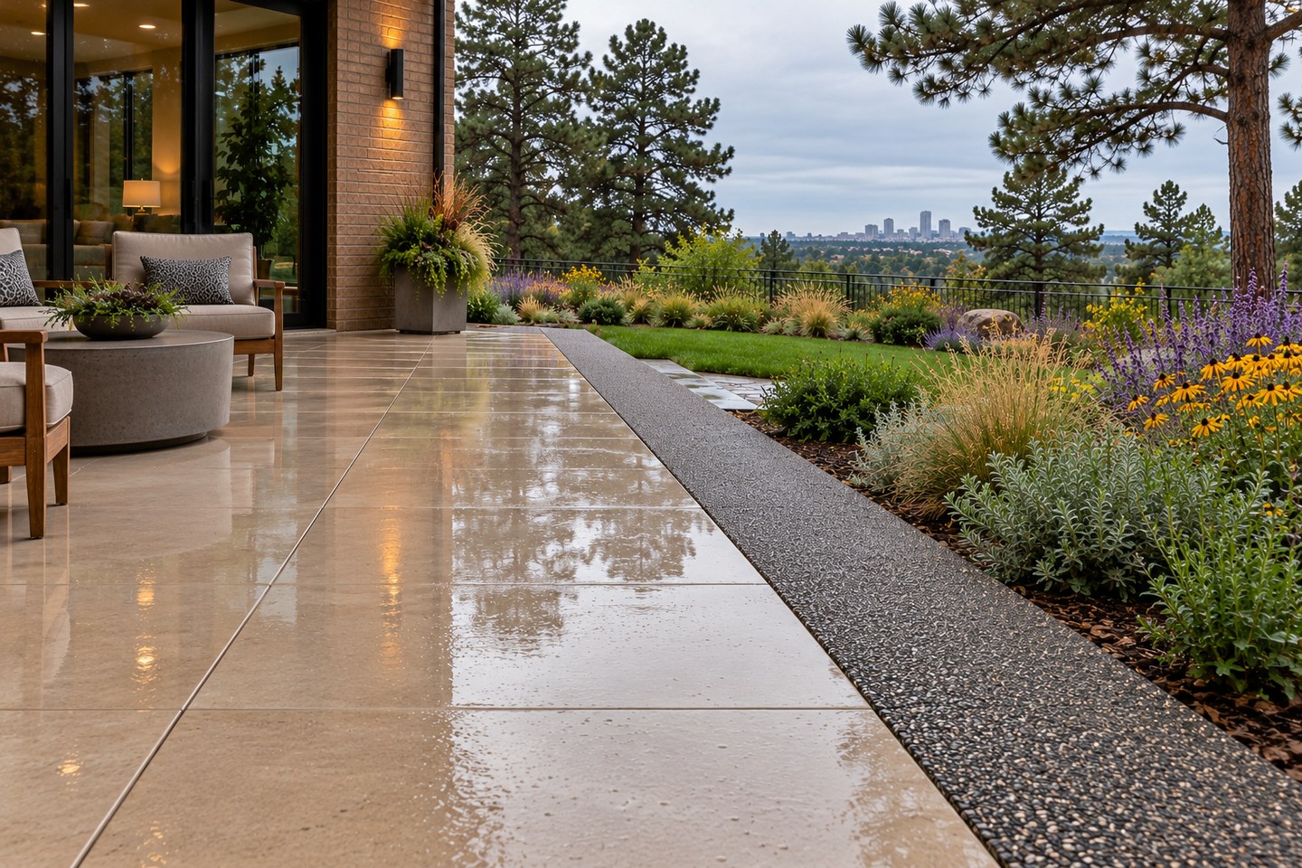
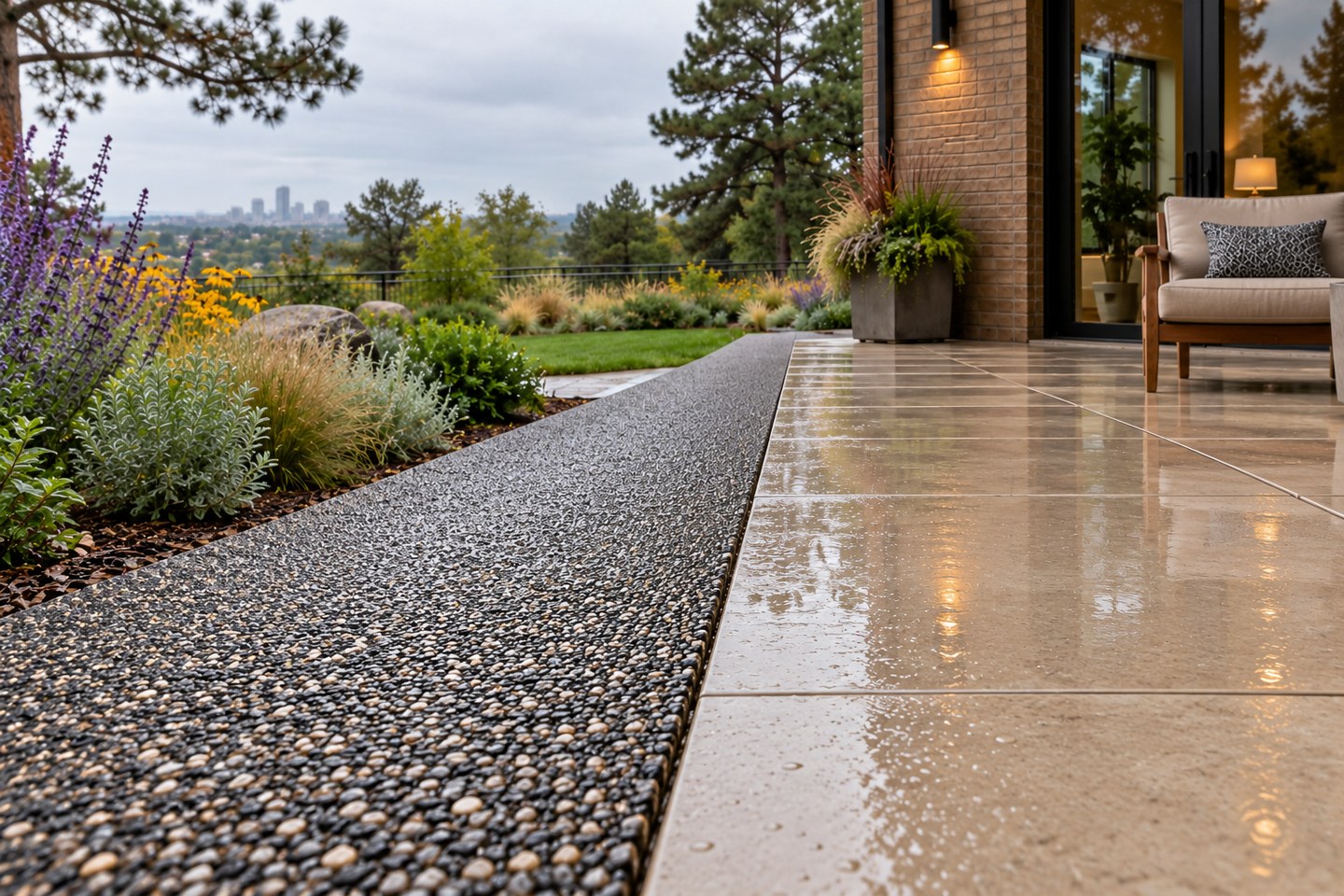
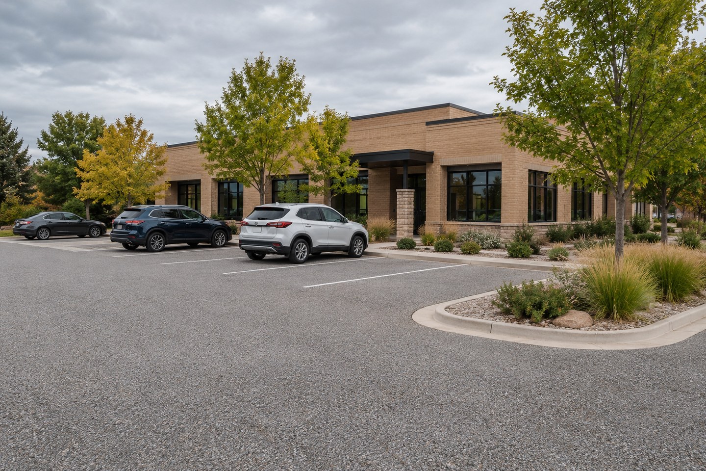
COLORADO / FROM EVERY ANGLE

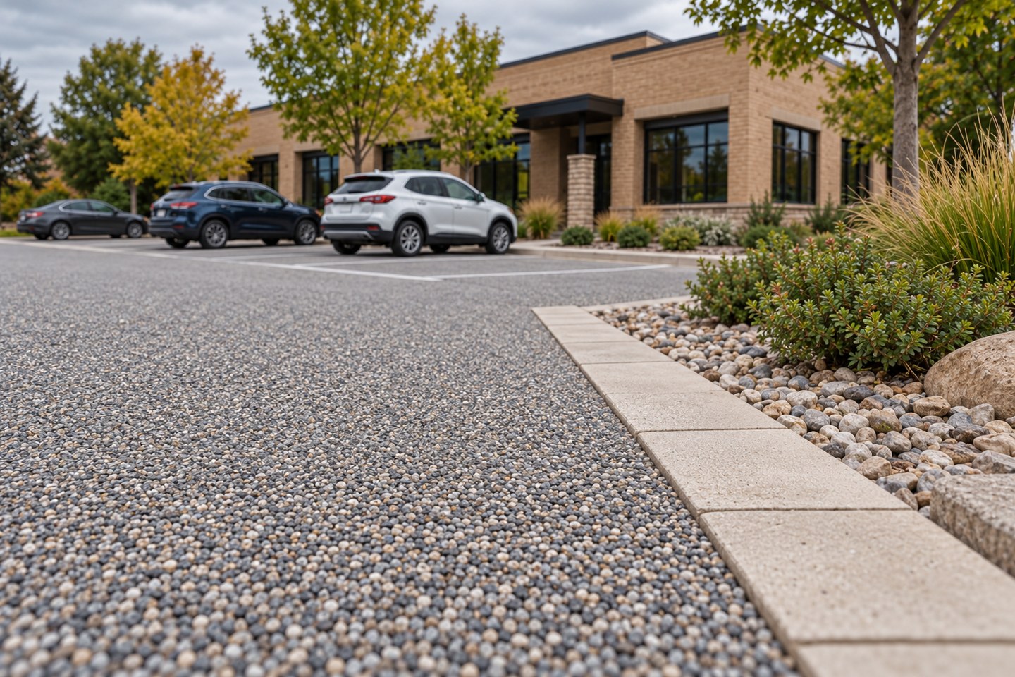
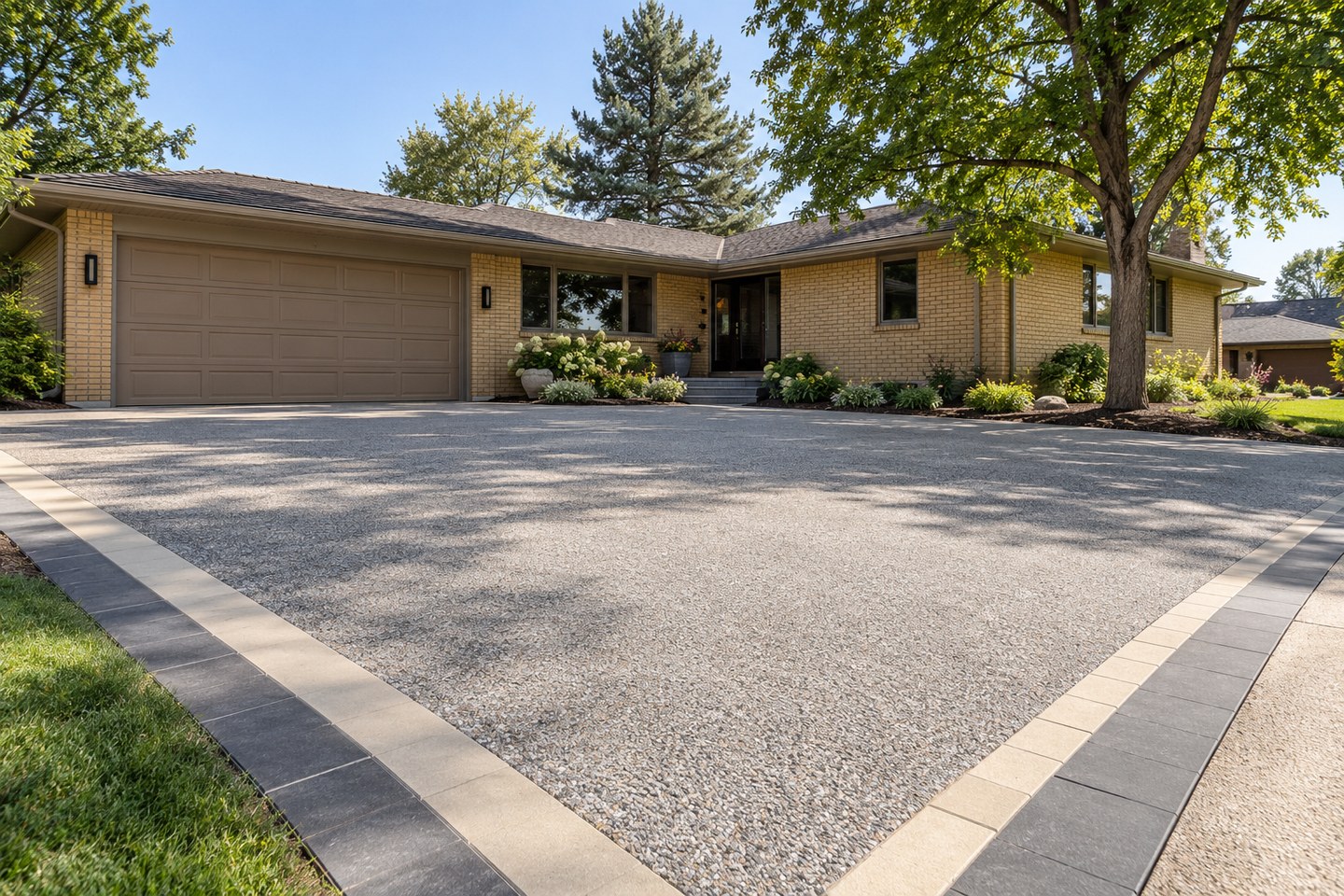
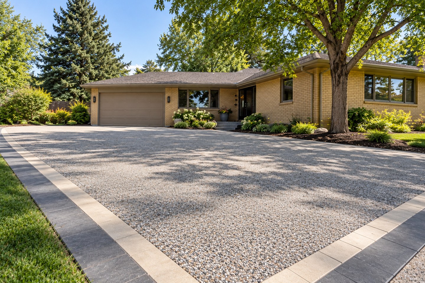
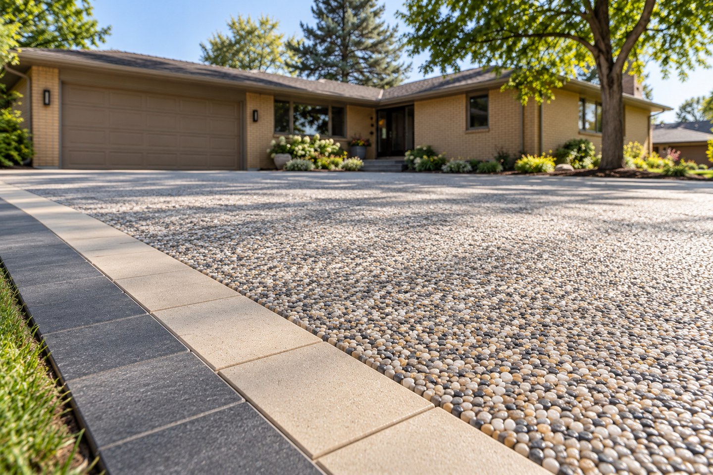
YOUR NEXT CHAPTER
Bring a few photos, your location, and a sense of what you want to create.
Explore your project ↗